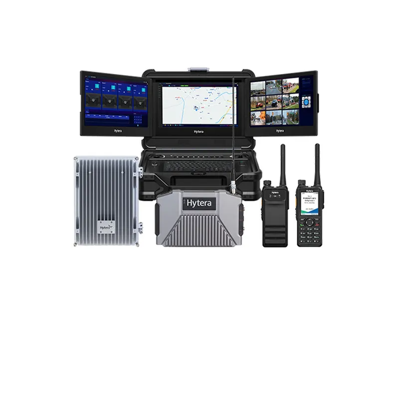
Hytera Ad Hoc Repeater Solution


Extending radio coverage across a large area is an engineering problem, not a purchasing decision. Antenna height, terrain, structures and receiver sensitivity determine range far more than transmit power does. TechnoRF plans coverage by link budget and terrain analysis, then verifies it by measurement.
Hytera Ad Hoc Repeater Solution
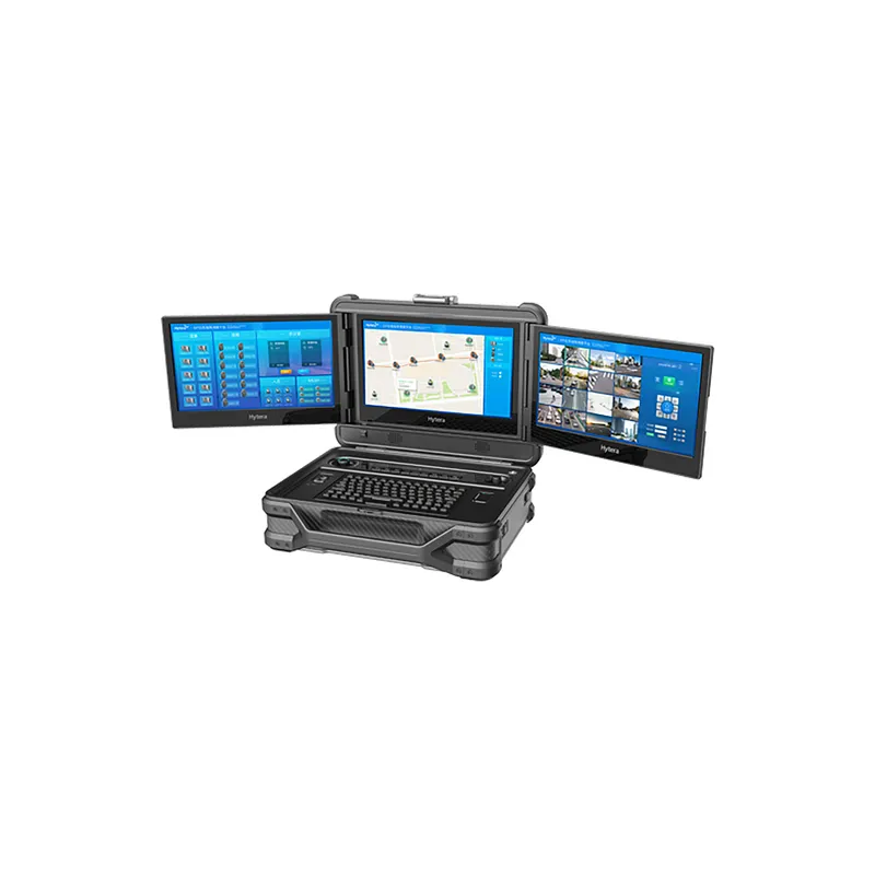
Hytera E-Center Portable Field Command and Dispatch Console
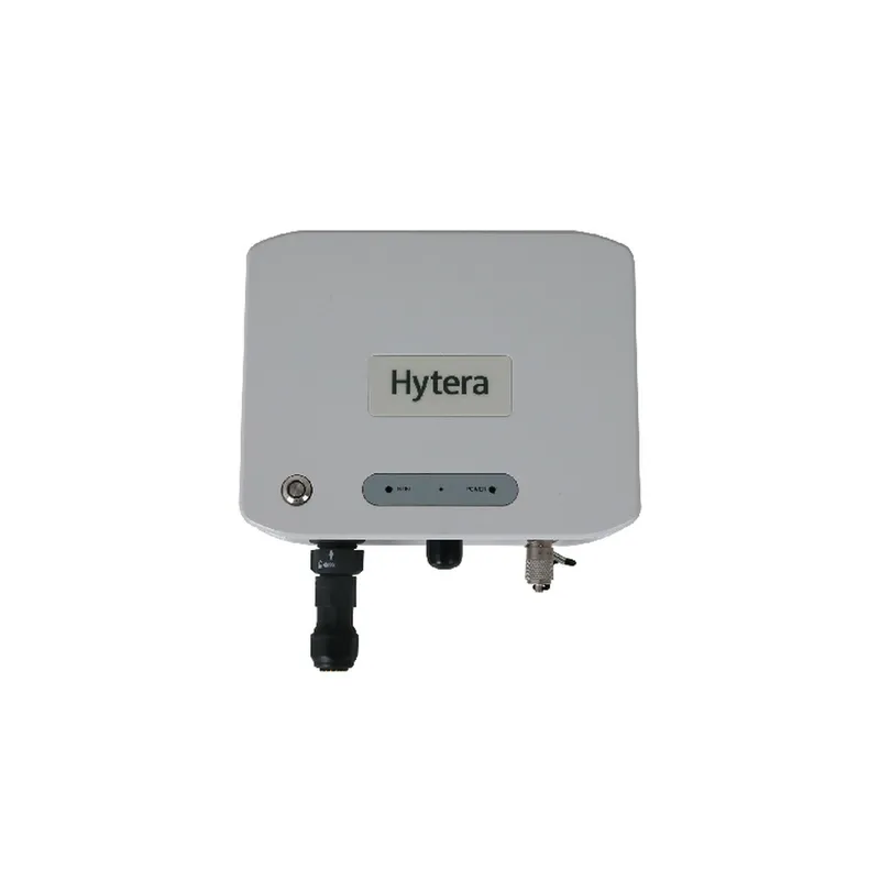
Hytera E-Pack Air100 Digital WANET Airborne Repeater
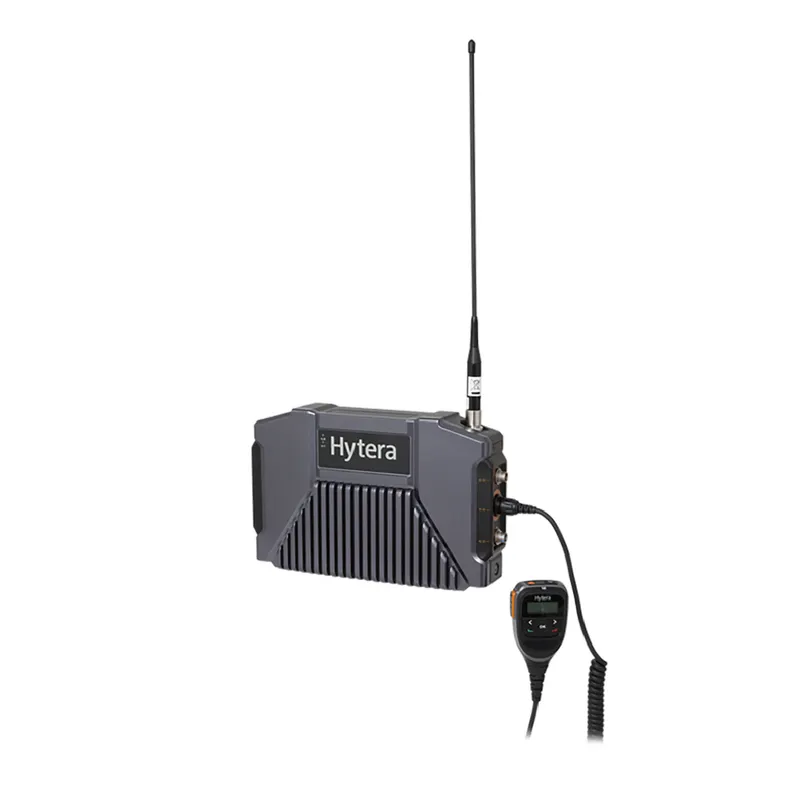
Hytera E-Pack TETRA100 Portable Ad Hoc Repeater
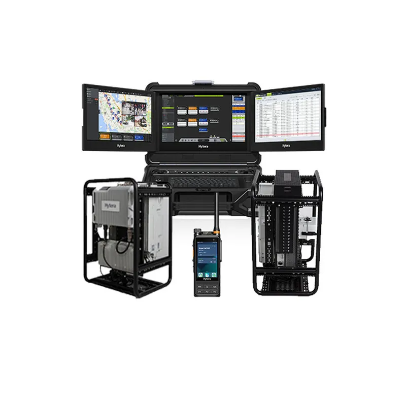
Hytera Fast Deployment Broadband Trunking Solution
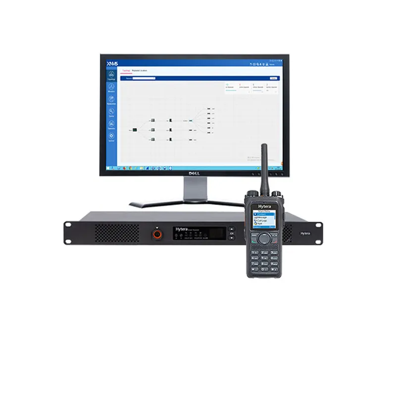
Hytera IP Multi-Site Solution
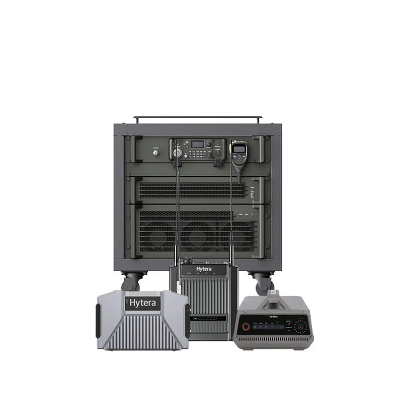
Hytera National Fast Deployment Voice Solution
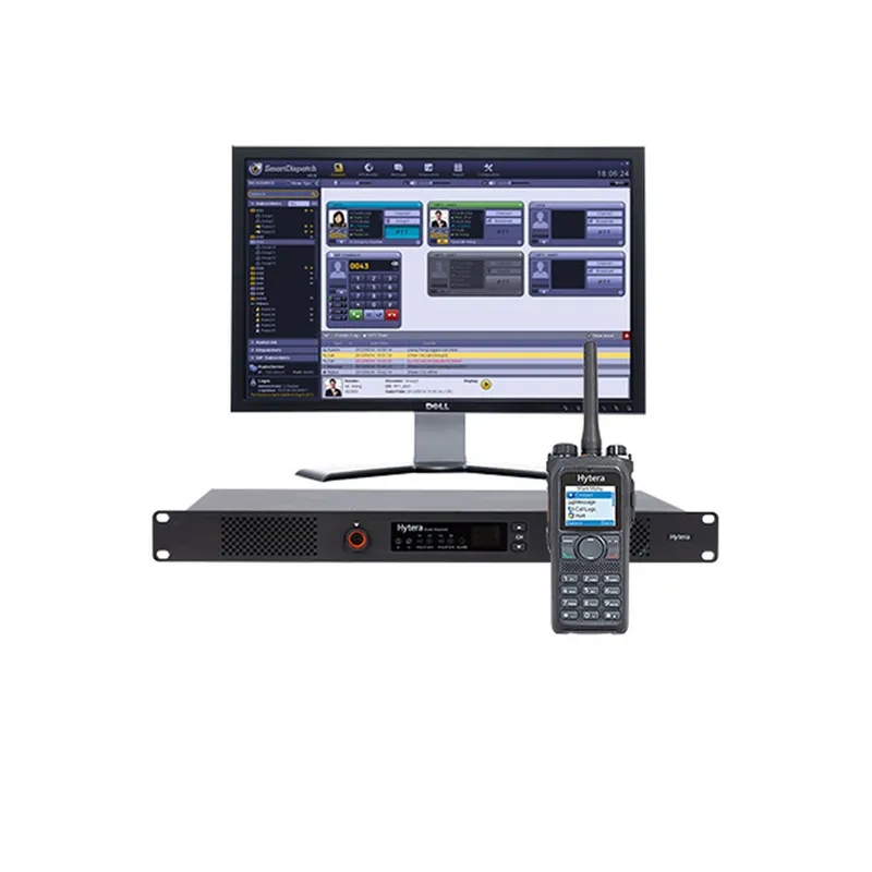
Hytera Single Repeater DMR Solution

AFAD — Disaster and Emergency Management Authority

Antalya Provincial Agriculture and Forestry Directorate

Atatürk University — High-Altitude Repeater Antenna

Çevre Industrial Estate Cooperative — Site-Wide Coordination

Istanbul Provincial Health Directorate — Citywide Health Communication

Istanbul Provincial Agriculture and Forestry Directorate

Karaman AFAD — Joint Disaster Repeater Overhaul

Karaman Special Provincial Administration — Repeater Restoration

Kars Provincial Health Directorate — Base Station Overhaul

Kocaeli Metropolitan Municipality — Multi-Service Field Communication

Marine Elektronik — Marina and Shipyard RF Coverage

Mersin University — Repeater-Backed Campus Digital Network

TRAC Edirne Branch — Portable Disaster Repeater

TRAC Headquarters — National HF/VHF Repeater Modernisation

TRAC Kocaeli Branch — Disaster Communication Support

Utopeak Outdoor — Communication on Trekking and Camp Routes
"We need better coverage" is the most common request in radio, and the most commonly answered by buying the wrong thing. Coverage is designed, measured and verified.
Antenna height, first and by a wide margin. The radio horizon in kilometres is approximately 4.12 × √h, with h in metres. Twenty extra metres of mast beats a doubling of transmit power in almost every case.
Terrain and structures. Hills block, valleys shadow, reinforced concrete attenuates, and metal-clad industrial buildings can be nearly opaque at UHF.
Receiver sensitivity. The link works in both directions, and the weak direction is normally the handportable transmitting a few watts from body height back to the repeater. A system designed only on the downlink will have users who can hear and cannot be heard.
Feeder and connectors. A long run of thin coaxial cable, or one badly made connector, can discard more signal than the power amplifier produces.
Transmit power, last. It is the specification printed on the box and the least significant of the five.
1. Define the requirement. Which areas, to what reliability, for which user types — handportable indoors is a far harder target than a vehicle radio outdoors. 2. Terrain and clutter modelling. Elevation and land-use data produce a predicted coverage map before anything is ordered. 3. Site survey. Candidate antenna positions assessed for height, access, power, structural capacity and backhaul. 4. Link budget. Calculated for the weakest realistic case, not the best one. 5. Design. Number and position of repeaters, antenna types, feeder specification. 6. Frequency planning and BTK licensing. 7. Installation and commissioning. 8. Verification measurement, with a report comparing measured signal against the plan.
Step 8 is where a project becomes accountable. Without it, "the coverage is fine" is an opinion.
| Situation | Approach |
|---|---|
| One site, coverage gaps indoors | Distributed antenna system or in-building repeater |
| Long enclosed volumes | Leaky feeder |
| Several sites, corporate network exists | IP multi-site linking |
| Several sites, no network | Microwave links |
| Users must not change channel | Simulcast |
| Fleet outside any practical footprint | PoC over cellular |
Obstruction, multipath cancellation, enclosure attenuation, or simply the edge of coverage. They have different causes and different fixes, and identifying which one you have takes a measurement — which is cheaper than the amplifier that would not have helped.
Coverage also changes over time. A new building, a grown treeline or a re-clad roof will alter a picture that was correct at handover. Periodic re-measurement is part of maintaining a system, not a sign that the original design was wrong.
Prediction map, site survey report, link budget, design, licence file, commissioning records and a measured verification report. Get in touch to have your site assessed.
Far less than people expect. Doubling transmit power adds 3 dB, which typically extends range by around a quarter in open terrain and much less among buildings — and it does nothing for the return path from a handportable, which is usually the weaker direction. Raising the antenna, improving the feeder or adding a repeater all deliver more, for less.
Through a link budget: transmit power, minus feeder and connector losses, plus antenna gains, minus the path loss predicted from terrain and clutter data, compared against the receiver’s sensitivity. The margin left over is what tolerates a user standing behind a wall. Terrain modelling then shows where that margin runs out, which is where the dead zones will be.
Almost always one of four causes: an obstruction blocking the path, a reflective structure causing signals to cancel, a metal or reinforced-concrete enclosure attenuating everything, or simply being beyond the coverage edge. The four have entirely different remedies, which is why the fix begins with measurement rather than with buying an amplifier.
The radio horizon in kilometres is roughly 4.12 × the square root of antenna height in metres, and it applies to both ends. A repeater antenna 30 m up sees about 23 km; a handportable at 1.5 m sees about 5 km; together, around 28 km in flat open terrain. Real terrain, buildings and vegetation reduce that, sometimes drastically.
The Hytera product range, TechnoRF engineering, installation, maintenance, technical service and business continuity planning — brought together into a system designed for how your operation actually works.
We deliver not only what you need, but more than you expect .