Radio Network Integration


Running an independent radio system at each location gives each site communication and gives the organisation none. IP multi-site architecture links repeaters so talkgroups span locations, users roam, and one control room sees the whole operation — with the IP network becoming a radio parameter.
An organisation with five locations often has five radio systems, bought at different times by different people, on different channels, with different naming. Each site can talk to itself. The organisation cannot talk to itself at all.
Multi-site architecture is the decision to treat those five systems as one.
The purchase looks cheaper and the operation is not.
No cross-site communication. A supervisor at one location cannot reach a team at another without a telephone, which defeats the reason radio exists.
No central visibility. Nobody sees the whole operation. Incidents at one site are reported to the centre after the fact rather than heard as they happen.
Divergent configuration. Each site's channel plan drifts to local preference. A radio carried from one site to another is useless, and staff who work across sites carry two.
Multiplied support. Five suppliers, five sets of spares, five programming toolchains, five service arrangements — and no way to move a spare device between locations.
Inconsistent safety behaviour. The emergency button does different things at different sites, which is the least acceptable of the five.
The standard answer for a commercial organisation is to link repeaters over an IP network so that they behave as a single system.
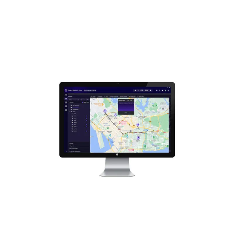
A call on a talkgroup is carried to every site where that talkgroup is present. A user moving from one site's coverage into another's re-registers automatically and stays in their groups. One dispatch position sees the whole network.
What that requires:
This is the point that surprises organisations, and it is worth stating clearly.
Once repeaters are linked, the quality of the IP path is audible. Bandwidth per site is modest — compressed voice is small — but latency, jitter and packet loss are not forgiving. Variable delay produces broken or robotic audio, and users report it as a radio fault.
So the design has to state:
That last item deserves testing rather than assuming. A well-configured system falls back to local operation on link failure: each site keeps working internally and only cross-site traffic is lost. A system that has not been configured for it goes silent at a location because a router restarted.
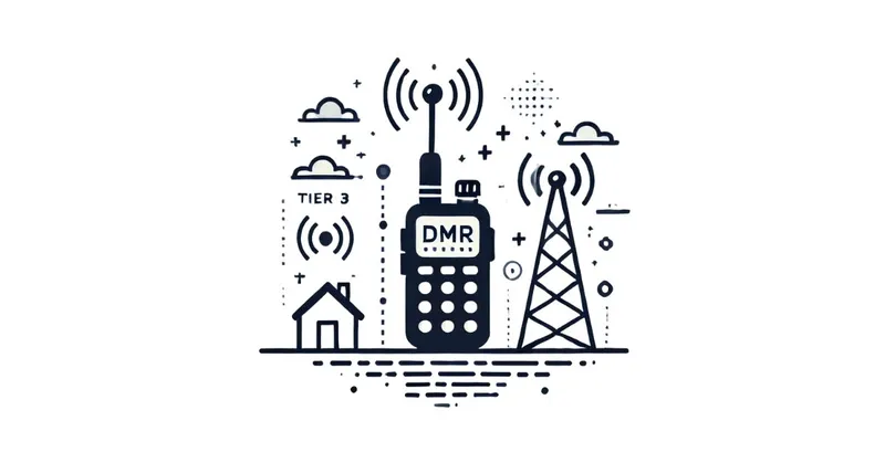
Where user density is high, Tier III trunking across the linked sites raises capacity substantially: channels are assigned from a pool per call rather than dedicated per talkgroup, priority levels are honoured, and the system handles peaks without a queue forming on one group.
For very large or critical operations, TETRA extends the same idea further with guaranteed setup times, pre-emption and site-level redundancy designed in.
Central management is where the architecture pays back, because the questions a control room asks are organisational:
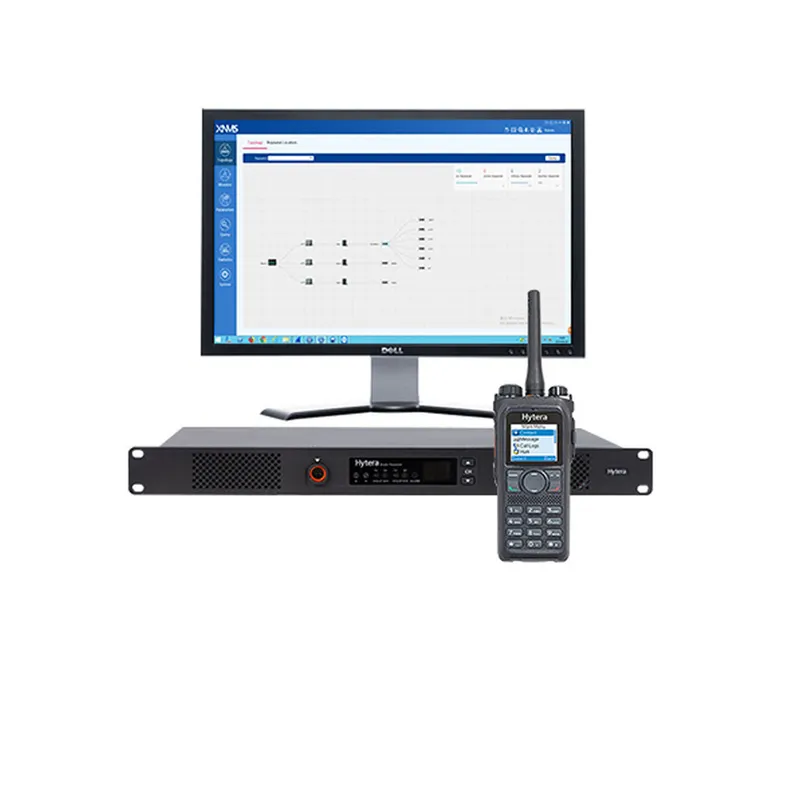
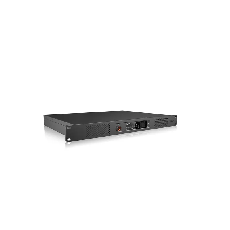
The last one changes support economics. Network management tools — Hytera's XNMS in this ecosystem — turn "the radios are not working at the Ankara site" into an alert that arrived an hour earlier.
Central management only works if the configuration is central.
One talkgroup plan across all sites, with local groups where genuinely local and shared groups where not. One ID plan with reserved blocks per location. One master codeplug per model, versioned and owned by the organisation. One naming convention, so a radio reads the same everywhere.
Consolidating five divergent systems into one plan is real work, usually a renumbering exercise, and it is the largest single task in a multi-site project. It is also the one that produces most of the benefit.
Linking sites does not create coverage. Each location needs its own survey and acceptance criterion, because a warehouse in one city and an office in another are different RF problems.
Where sites are close enough for their coverage to overlap, that overlap is designed rather than left to chance: clean roaming needs deliberate overlap, and adjacent sites need frequency planning so they do not interfere.
Multi-site systems concentrate risk in two places, and both need answers in the design:
Because it works locally and fails organisationally. Nobody can call between sites, there is no central visibility, each site drifts to its own channel plan, and a fault at one location is invisible to whoever supports it. Separate systems are cheaper to buy and considerably more expensive to run.
Adequate bandwidth per linked site — modest, since voice is compressed — but above all low and stable latency and reliable availability. Once repeaters are linked, jitter and packet loss become audible as broken audio, so the network becomes part of the radio system rather than a background service.
Yes, that is the point of linking. A radio moving from one site's coverage into another's re-registers and stays in its talkgroups, so the user notices nothing. Making that work cleanly requires deliberate overlap between site coverage, which is a design decision rather than an accident.
In a properly designed system, each site falls back to local operation: people at that location still talk to each other, and only cross-site traffic is lost. That behaviour has to be configured and tested — a link failure that silences a whole site is a design that assumed the network never fails.
The Hytera product range, TechnoRF engineering, installation, maintenance, technical service and business continuity planning — brought together into a system designed for how your operation actually works.
We deliver not only what you need, but more than you expect .